Toyota Airjet Looms (JAT Series) are engineered to operate at maximum speed and high stability, posing a significant challenge to maintenance teams. The complexity of the high-speed pneumatic system, combined with the precision weaving mechanism, requires the maintenance and replacement of Toyota Airjet loom components to strictly adhere to the manufacturer’s technical standards.
Any inaccuracies in calibration, especially concerning the weft insertion and main drive components, will lead to a substantial decrease in OEE (Overall Equipment Effectiveness), an increase in fabric defect rates, and uneven wear. This in-depth technical guide provides detailed instructions on the inspection, diagnosis, and replacement procedures for the most critical Toyota Airjet loom components, applicable to the most popular JAT series models today.
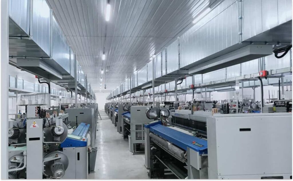
Modern textile manufacturing relies entirely on the speed and accuracy of the equipment. Toyota Airjet looms have demonstrated their leading position through their ability to run continuously at speeds up to 2,000 meters of weft yarn per minute. However, to sustain this performance, technical intervention must always be timely and precise.
The Toyota Airjet loom components operate in a harsh environment: subjected to high friction, continuous contact with pneumatic pressure, and fiber dust. Therefore, managing the lifecycle of key parts—from Main Nozzles and Solenoid Valves to main drive components (Sley Drive)—is a deciding factor in a factory’s success.
We will go beyond routine cleaning procedures. This manual delves into engineering physics, including how to check torque, calibrate the crank angle, analyze sensor signals, and build an optimal spare parts inventory management strategy. The goal is to help your technical team enhance diagnostic capabilities, execute accurate Toyota Airjet loom components replacement, minimize downtime, and maximize product quality.

1. In-Depth Analysis of the Pneumatic System: The Heart of the Airjet Loom
The pneumatic system is the most sensitive area and determines the weaving performance of the Toyota Airjet loom. The precision of the airflow is controlled by the coordination between the air nozzles and the solenoid valves.
1.1. Main Nozzles and Sub Nozzles: Physics and Wear
Air nozzles are responsible for creating a concentrated airflow to propel the weft yarn across the weaving width.
1.1.1. Wear Mechanisms and Consequences
- Wear Caused by Yarn: The weft yarn, especially blended or highly twisted types, creates continuous friction inside the nozzle bore. This alters the shape and diameter of the air exit hole, leading to a degradation of air stream collimation.
- Wear Caused by Fiber Dust: Fiber fluff and contaminants in the compressed air are compacted onto the nozzle wall, causing localized blockages and air stream turbulence.
Consequences: When the nozzle wears, the pressure required to propel the weft yarn increases, leading to higher energy consumption. More importantly, the accuracy of the weft insertion stop point is deviated, causing weaving defects like tuck-in errors or weft breakage.
1.1.2. Technical Inspection Procedures for Air Nozzles
- Visual Inspection (Optimization): Use a magnifying glass or handheld microscope to inspect the nozzle bore walls, looking for scratches, concave wear marks, or stubborn contamination.
- Back Pressure Test: Use specialized measuring equipment to check the compressed air back pressure at the nozzle tip. High back pressure indicates nozzle blockage.
- Periodic Replacement: Air nozzles, despite no obvious failures, should be replaced after a certain operating cycle (typically 8,000 to 12,000 running hours), especially when weaving high-precision yarn types.
1.2. Pneumatic Solenoid Valves
Solenoid valves control the timing and amount of air discharge.
1.2.1. Failure Analysis and Technical Requirements
- Slow Response Time: Due to coil or internal spring fatigue, the valve opens/closes slower than the signal from the main control board. This causes a deviation in the actual Weft Insertion Angle compared to the set angle.
- Valve Leakage: Internal rubber seals become rigid or torn due to heat and chemicals in the compressed air. Leakage reduces system pressure and wastes energy.
1.2.2. Solenoid Valve Replacement Technique
- Absolute Air Discharge (Zero Pressure): It is mandatory to discharge all compressed air from the related pipelines before removing the valve.
- Resistance Check: Measure the resistance of the new Solenoid coil (typically 18-25 Ohms, depending on the model) to ensure the coil is not open or short-circuited.
- Installation and Sealing: Use appropriate sealant for thread connections and tighten to the specified torque. Incorrect installation or loose tightening can cause immediate leakage.
- Functional Check: After replacing this Toyota Airjet loom component, perform a test run at low speed and monitor the valve’s response time using a specialized meter.
2. Main Mechanical Drive Toyota Airjet Loom Components
The mechanical drive system is responsible for the movement of the Sley, the Shedding mechanism, and the Let-Off/Take-Up motions.
2.1. Sley and Drive Gears
The Sley is the part that pushes the weft yarn into the fell of the cloth. It bears the largest mechanical load.
2.1.1. Inspection of Sley Drive Gear Wear
Signs of Wear: Loud noise, abnormal vibration, and especially uneven warp yarn tension/contraction due to Sley movement backlash.
Inspection Procedure:
- Remove the protective cover and visually inspect the tooth surface of the main Sley Drive Gear and intermediate gears.
- Use a feeler gauge to measure the backlash between the teeth. Backlash exceeding the limit (typically 0.15 mm – 0.25 mm depending on the model) indicates that this Toyota Airjet loom component must be replaced.
2.1.2. Sley Drive Gear Replacement (Detailed Example)
- Mark Position: Mark the timing marks on the main shaft and the gear.
- Remove Brake/Clutch: If applicable, remove the brake/clutch assembly from the shaft.
- Remove Gear: Use a specialized gear puller to gently remove the old gear. Absolutely do not use a hammer as it can damage the bearings or deform the shaft.
- Install New Gear: Clean the shaft and install the new gear. Use a heat gun to slightly warm the new gear (max 100 C) to facilitate smoother installation.
- Timing Alignment: Reinstall and align the marked timing marks. Adjust the gear backlash to the standard level.
2.2. Shedding System
This system controls the Heddle Frames to create the Shed.
- Cam Shedding Looms: Check the wear of the rollers and the cam surface.
- Dobby/Jacquard Looms: Check control cables and electronic components. Worn or loose cables need replacement to ensure the precision of the Shed opening.
2.3. Take-Up and Let-Off Systems
Signs of Failure: Fabric has horizontal streaks (Barre) or uneven Pick Density (PPI).
Components to Watch: The Take-Up gearbox gears and the Let-Off motor speed sensors. Replacement of these Toyota Airjet loom components is mandatory if any deviation occurs.
3. Management and Replacement of Electronic Components – The Eye of the Airjet Loom

Toyota Airjet looms rely heavily on electronic sensors to maintain speed and quality.
3.1. Weft Detector/Sensor
This sensor detects the presence of the weft yarn after insertion.
Operating Principle: Typically uses optical or piezoelectric sensors.
Failure Analysis:
- False Stop: Occurs when the sensor reports a yarn break when the yarn is still present. This is usually due to contamination or fiber dust on the sensor surface, or the sensor being misaligned.
- Missed Stop: The machine does not stop when the weft yarn breaks. This is often due to a damaged sensor or a faulty circuit.
Replacement and Calibration: When replacing the sensor, a specialized measuring tool must be used to calibrate the clearance and angle, ensuring the optical/electrical signal is accurately transmitted to the main control board.
3.2. Main Control Board (PCB)
The main control board is the brain that manages the entire weaving process.
Signs of Failure: Random error messages displayed on the screen, control functions not responding, or the machine failing to start.
Replacement Procedure:
- Data Backup: It is mandatory to back up all Set Parameters and Fabric Style Data before removing the old board.
- ESD Compliance: Use an ESD wrist strap to protect the new board from damage caused by static electricity.
- Connection Check: Ensure all ribbon cables and power connectors are tightly and correctly plugged in.
4. Toyota Airjet Loom Components Management Strategy (Spare Parts Inventory)
Effective management of the spare Toyota Airjet loom components inventory is key to reducing unplanned machine downtime.
4.1. Component Classification by Priority Level
- Level A (Critical): Toyota Airjet loom components that cause prolonged downtime, are difficult to procure, and have a long Lead Time. Examples: Main control board, main motor, large drive gears, complex Solenoid valve clusters. Must always be stocked.
- Level B (Necessary): Toyota Airjet loom components that wear quickly, require periodic replacement, and are easier to procure. Examples: Main/Sub air nozzles, cutters, yarn sensors, seals. Stock according to consumption cycle.
- Level C (Optional): Parts that rarely fail, or can be repaired/fabricated on-site. Examples: Machine covers, protective caps.
4.2. Calculating the Reorder Point (ROP)
ROP is a formula used to determine when to order new Toyota Airjet loom components to avoid running out of stock during the Lead Time.
ROP = (Daily Consumption Rate \times Lead Time) + Safety Stock
Applying ROP to Level A and B Toyota Airjet loom components ensures the factory always has replacement parts available.
4.3. Parts Quality Management (Sourcing Strategy)
- Use OEM Only: Although the price is higher, OEM Toyota Airjet loom components ensure material compatibility and tolerance, protecting other parts and extending machine life.
- Check Certification: Always require Certificates of Origin (CO) and Quality (CQ) from reliable suppliers like VieTextile.
5. Advanced Calibration Procedure After Component Replacement
After replacing critical Toyota Airjet loom components, calibration is mandatory to ensure the machine operates at optimal performance.
5.1. Clearance and Parallelism Calibration
- Sley Clearance: Use a Dial Gauge to check the parallelism and clearance between the Sley and the Reed at all positions across the weaving width. Even a small deviation in parallelism causes Reed wear and warp yarn breakage.
- Shaft Parallelism: Check the parallelism of the Main Shaft and other drive shafts.
5.2. Weft Insertion Timing Calibration
This is the most critical step and requires a technician to use electronic angle measuring equipment.
- Determine Shed Closure Angle: Typically 350 to 10 of the main shaft.
- Pneumatic Timing Adjustment: Adjust the Solenoid valve opening time so that the Main Air begins propelling the weft yarn exactly at a specific main shaft angle (e.g., 300 to 310).
- Sub Air Adjustment: Calibrate the timing and position of the sub-nozzle clusters to maintain the weft yarn speed and tension as it travels across the weaving width. Replacing Sub Air-related Toyota Airjet loom components (like valves) will require recalibration of this entire timing sequence.
5.3. Run-in Procedure After Major Maintenance
After replacing major mechanical components, the machine requires a run-in procedure for the new parts to seat and normalize.
- Low-Speed Running: Operate the machine at 50% of maximum speed for 2-4 hours.
- Temperature Check: Monitor the temperature of newly installed bearings, gears, and motors. A sudden or excessive temperature increase is a sign of incorrect installation or lack of lubrication.
- Torque Re-tightening: After 24 hours of operation, check and re-tighten the torque of critical screws and bolts (e.g., motor mounting bolts, Sley shaft bolts) to prevent loosening due to vibration.
6. Failure Analysis of Toyota Airjet Loom Components and Troubleshooting Solutions
Understanding the root cause of failure helps prevent recurring breakdowns.
6.1. Air Nozzle Failure – Flow Analysis
| Sign of Failure | Root Cause | Technical Solution |
| Air pressure increase by 15-20% | Worn nozzle, changed exit hole shape | Replace the Toyota Airjet loom component with a new OEM nozzle. Check inlet compressed air pressure. |
| Frequent weft breaks near the fabric edge | Insufficient Sub Air speed or incorrect timing | Clean or replace the Solenoid valve, recalibrate Sub Air timing according to the main shaft angle. |
| Tuck-in failure | Excessive tuck-in mechanism clearance or dull cutter blade | Adjust clearance, replace cutter blade. Check air pressure at the Tuck-in Nozzle. |
6.2. Mechanical Failure – Vibration Analysis
- Excessive Vibration: Often due to uneven Sley gear wear or damaged bearings. Bearings or gears must be replaced, and shaft alignment checked simultaneously.
- Loose Connections: Use appropriate thread lockers for bolts subjected to high vibration after replacing mechanical Toyota Airjet loom components.
7. Safety and Environmental Standards When Handling Components

Ensuring safety and adhering to waste disposal regulations is mandatory.
7.1. LOTO (Lockout/Tagout) Rules
Mandatory: Before performing any Toyota Airjet loom components replacement (especially electrical and mechanical parts), the technician must disconnect the main power source and lock/tag the main switch to prevent unintended machine operation.
Discharge Residual Energy: Always discharge all compressed air and ensure all moving parts have stopped completely (Zero Energy State).
7.2. Industrial Waste Disposal
- Electronic Components: Boards and damaged sensors must be treated as hazardous Electronic Waste (E-Waste).
- Greasy Components: Oil-soaked bearings and gears must be separately categorized and handled according to environmental regulations to prevent pollution.
8. Detailed Guide for Main Nozzle Replacement and Calibration
Since the air nozzle is the most critical Toyota Airjet loom component, the replacement procedure needs to be detailed.
8.1. Tool and Position Preparation
Tools: Torque Wrench, specialized nozzle removal tool, Angular Gauge for main shaft rotation, and thread sealant (Teflon Tape or Thread Sealant).
Machine Position: Rotate the main shaft to 350 (or the removal angle specified by Toyota).
8.2. Replacement Steps
- Disconnect: Remove the compressed air hose and control cable (if any) from the nozzle cluster.
- Remove Old Nozzle: Use the specialized removal tool to gently unscrew the old nozzle. Check the O-ring or metal washer.
- Clean Installation Chamber: Extremely important. Absolutely clean the installation chamber to remove fiber dust and contaminants.
- Install New Nozzle: Install a new O-ring or washer. Install the new nozzle and hand-tighten first.
- Accurate Torque Tightening: Use the torque wrench to tighten the nozzle to the specified value (typically 15 Nm to 20 Nm). Overtightening will deform the nozzle housing and chamber; loose tightening causes leakage.
8.3. Post-Installation Calibration
- Nozzle Height Calibration: Use a specialized ruler to check the height from the nozzle tip to the Reed edge. Height deviation affects the air stream collimation.
- Operational Pressure Check: Start the machine and check the compressed air output pressure of the new nozzle. Compare with the Specification and adjust the pressure regulating valve if necessary.
- Timing Check: Monitor the Solenoid signal and weft insertion timing on the control screen to ensure no deviation after replacing this Toyota Airjet loom component.
9. Analyzing Differences and Optimization by Machine Series
Despite sharing the Airjet principle, different JAT series models have varying maintenance requirements.
9.1. Toyota JAT710 (High Mechanical Durability)
Maintenance Focus: JAT710 often uses a more traditional mechanical (or electromagnetic) clutch and brake system. The brake shoes and Clutch Disc need thorough inspection.
Electronic Components: Although less complex than the JAT810, electronic Toyota Airjet loom components in the JAT710, such as ICs on the board, may be harder to source due to obsolescence. Prioritize stocking these components.
9.2. Toyota JAT810/JAT800 (Modern Speed and Electronics)
Maintenance Focus: Direct Drive system uses servo/AC motors instead of clutches, minimizing wearing mechanical parts. However, it requires higher precision from position sensors (Encoders).
Electronic Components: Motor control boards, especially the Inverter, are expensive and sensitive Toyota Airjet loom components. Maintenance must include checking the cleanliness and temperature of the Electrical Cabinet. Failures on the JAT810 are typically electronic rather than mechanical.
10. Conclusion and Next Steps
The correct maintenance and replacement of Toyota Airjet loom components is a continuous process that requires a combination of deep technical knowledge, precise tools, and smart parts management strategy. From checking the air pressure at the nozzle to calibrating the Sley gear backlash within a few tens of micrometers, every detail affects weaving quality and productivity.
Do not settle for sub-optimal performance or the risk of sudden machine stops due to low-quality Toyota Airjet loom components. Partner with a reliable Toyota Airjet loom components supplier who offers expert technical consultation to ensure your machine always operates at its best.
VieTextile commits to providing a comprehensive solution for your textile factory: genuine Toyota Airjet loom components, technical consulting services, and standardized maintenance procedures.
Act now to optimize your performance and profitability! Contact us to receive detailed quotes and a schedule for specialized maintenance checks:
Contact Information:
Hotline: 0901 809 309
Email: info@vietextile.com
Website: https://vietextile.com